Info@sanjaay.com

Private, multi-server LLM capacity with task-based model routing behind one internal API.
Multi-GPUGGUFQuantizationFastAPIModel routing
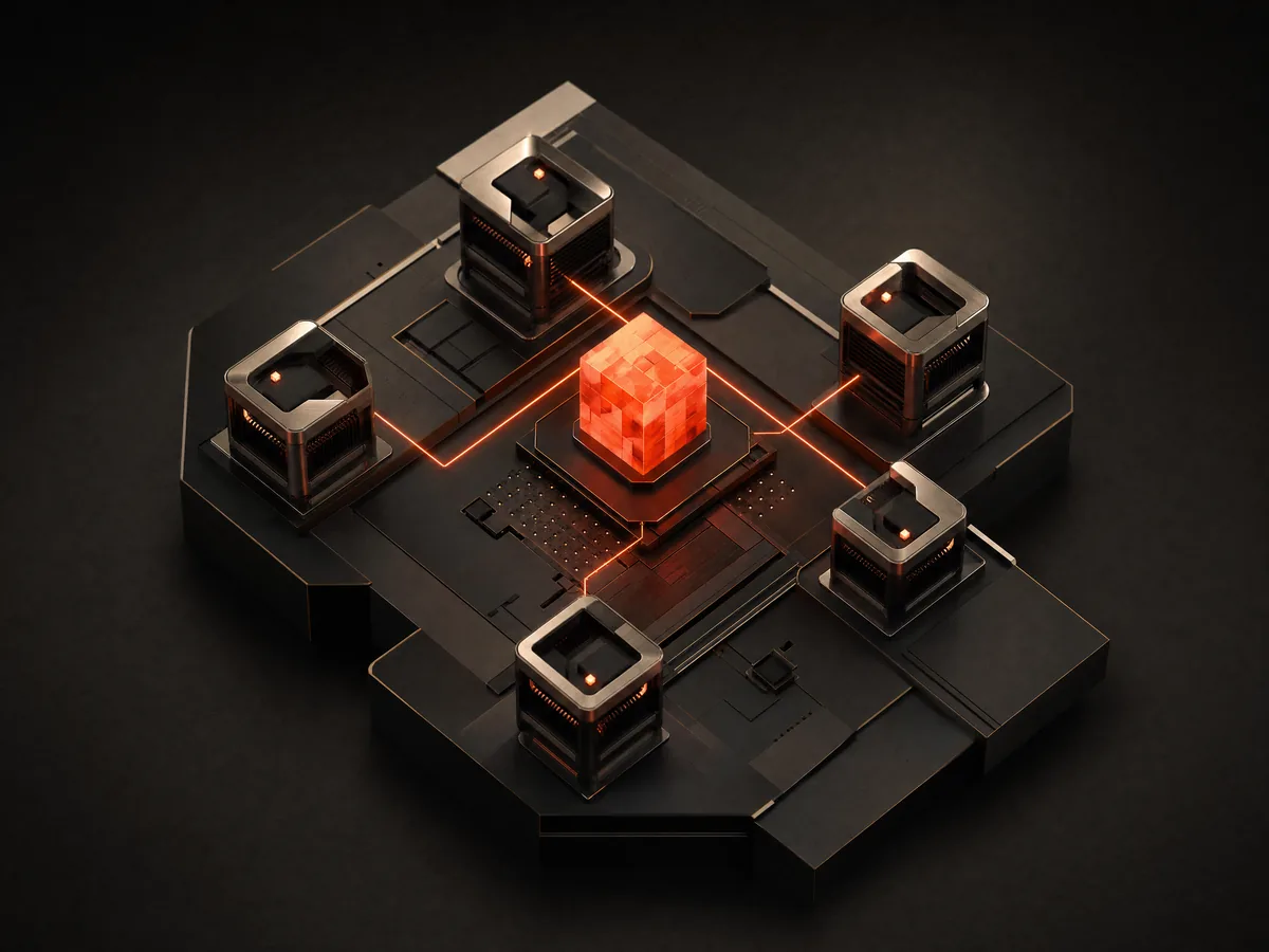
Five compute modules connected to a coral core, an illustration of distributed AI inference
System study / 01
Architecture flow 5 STAGES
  1. 01Internal tools
  2. 02API gateway
  3. 03Task router
  4. 04Model pool
  5. 05GPU nodes

The challenge

Internal tools needed dependable language-model capacity. Third-party APIs meant handing over internal data, accepting variable latency, and paying per token for workloads that ran constantly.

Architecture

Several high-memory GPU servers host a pool of quantized models behind one OpenAI-compatible gateway, so every tool integrates once and never learns about the hardware. A router sends each request to the model suited to it, a queue bounds concurrency per node, and a hosted API stays configured as a fallback.

Technical decisions

Quantization was set per model against measured VRAM headroom rather than applied uniformly, because over-quantizing a reasoning model degrades output in ways that are expensive to debug downstream. Context length was derived from concurrency targets, since both compete for the same memory. A small fast model handles classification, so cheap work never occupies expensive capacity.

Responsibilities

  • GPU and VRAM capacity planning
  • Model evaluation and quantization strategy
  • Gateway, routing and serving stack
  • Monitoring, alerting and failover

Engineering considerations

  • VRAM traded against context length and concurrency
  • Power and thermal headroom under sustained load
  • Quality regression from aggressive quantization
  • Keeping the gateway stable as models change behind it

Technologies

Ubuntu ServerMulti-GPU NVIDIAGGUFllama.cppPythonFastAPIDockerNginx
THE OUTCOME

Internal tools call one endpoint and get whichever model fits the task. Capacity grows by adding a node, and the data stays on infrastructure that is directly controlled.


Live broadcast processed as it happens: transcription, OCR and event detection into a structured operator feed.

Live ingestSpeech-to-textOCRWebSocketsLow latency
A waveform passing through smoked glass, an illustration of real-time media analysis
System study / 02
Architecture flow 5 STAGES
  1. 01Live ingest
  2. 02Audio + frames
  3. 03STT / OCR / vision
  4. 04Event detection
  5. 05Operator feed

The challenge

A live broadcast carries more information than an operator can track. The work was to understand it while it was still happening, without ever putting the live signal at risk.

Architecture

Video is split on ingest: one path continues untouched to recording and distribution, the other feeds analysis. Audio streams into speech-to-text, sampled frames run OCR and a vision model, and a detection layer turns those signals into timestamped events pushed over WebSockets to an operator dashboard.

Technical decisions

Frames are sampled rather than processed exhaustively, since full-rate vision inference buys accuracy nobody can act on. The language model sits off the critical path: detection stays deterministic and fast, enrichment arrives a moment later. Every queue is bounded with an explicit drop policy, so under pressure the system sheds analysis rather than backing up into the live feed.

Responsibilities

  • Pipeline design and latency budgeting
  • Model selection for transcription, OCR and vision
  • Stage isolation so analysis cannot stall the live path
  • Failure detection and recovery

Engineering considerations

  • Back-pressure, so live never blocks on analysis
  • Timestamp alignment across derived events
  • GPU contention with other inference workloads
  • Graceful degradation when a stage fails mid-broadcast

Technologies

OBSRTMPMedia serverSpeech-to-textOCRVision modelsFastAPIWebSockets
THE OUTCOME

Operators read a structured, timestamped feed instead of trying to catch everything by eye, and automated responses fire inside the live window.

One live input distributed to several destinations, with redundancy at the encoder, the edge and the connection.

RTMPMedia serverDual-WANFailoverOBS
A titanium sphere with coral signal rings, an illustration of broadcast infrastructure
System study / 03
Architecture flow 5 STAGES
  1. 01Encoder
  2. 02Local relay
  3. 03WAN failover
  4. 04Destinations
  5. 05Local recording

The challenge

One production needed to reach several destinations at once. Encoding per destination wastes capacity, and a single uplink makes the venue connection a single point of failure for the whole broadcast.

Architecture

One encoded output goes to a local media server that relays to each destination independently. Egress runs over dual-WAN with automatic failover, and a local recording is written continuously as the authoritative copy, independent of any network condition.

Technical decisions

Relaying locally rather than encoding per destination keeps CPU and uplink cost flat as destinations are added. Local recording is deliberately decoupled: if every network path fails, the material still exists. Reconnection uses backoff, because an outage plus aggressive retries produces a storm that hurts the healthy paths too. Failover was tested by physically pulling connections, not assumed from configuration.

Responsibilities

  • Topology and bandwidth planning
  • Hardware, network and audio chain
  • Failover configuration and rehearsed testing
  • Runbooks for the people operating it

Engineering considerations

  • Uplink budgeted per destination, not in aggregate
  • Encoder settings acceptable to every endpoint
  • Reconnect storms after a destination outage
  • Failover without a visible interruption

Technologies

OBSRTMPMedia serverLinuxDockerNginxDual-WANMonitoring
THE OUTCOME

One operator publishes to several destinations at once. A failed connection or destination degrades the broadcast instead of ending it, and the local recording survives regardless.

Repetitive multi-step workflows across systems with no API, executed and verified without a human watching.

PlaywrightAgent architectureQueuesRecoveryAudit
Architecture flow 5 STAGES
  1. 01Task queue
  2. 02Planner
  3. 03Executor
  4. 04Verifier
  5. 05Recovery

The challenge

Recurring workflows ran across web interfaces with no programmatic access. Done manually they consumed hours and varied every time. Naive scripting broke constantly, and worse, broke silently.

Architecture

An orchestrator pulls tasks from a queue and hands each to specialised agents. A planner decomposes it, an executor drives a Playwright session with stored authentication state, a verifier independently re-reads the resulting state, and a recovery agent retries or escalates. Every run is recorded step by step for audit.

Technical decisions

Deterministic selectors do the work wherever possible and the model is reserved for planning, because a model asked to click buttons fails in ways that are hard to reproduce. The verifier is a separate agent that re-reads state rather than trusting the report from the executor, since self-reported success is the most common source of silent failure. Steps are idempotent, so a retry cannot double-apply an action.

Responsibilities

  • Orchestration and agent boundaries
  • Structured tool interface for the agents
  • Retries, idempotency and task isolation
  • Audit logging and human escalation

Engineering considerations

  • Interfaces that change without warning
  • Session and credential lifetime on long jobs
  • Preventing duplicate side effects on retry
  • Staying inside the terms and rate limits of each system

Technologies

PythonTypeScriptPlaywrightNode.jsFastAPITask queuesSQLDocker
THE OUTCOME

Recurring work runs unattended and verifies itself. Failures surface as actionable alerts with the full run history attached, instead of quietly producing nothing.

A full-stack operations platform putting GPU, streaming and automation infrastructure behind an interface non-engineers can use safely.

ReactTypeScriptFastAPIWebSocketsAuth
Architecture flow 5 STAGES
  1. 01React dashboard
  2. 02REST + WebSocket
  3. 03FastAPI services
  4. 04Workers & queue
  5. 05Infrastructure

The challenge

The infrastructure was powerful and unusable by anyone except the person who built it. Every routine action meant an SSH session, which made one person a bottleneck for daily operations.

Architecture

A FastAPI backend exposes a task-oriented API with authentication and roles. A React and TypeScript frontend provides dashboards for GPU status, stream health and automation runs, with live state pushed over WebSockets. Long work runs on background workers with progress streamed back, and every state-changing action is audited.

Technical decisions

The database is the single source of truth and the UI subscribes to changes, because real-time interfaces built on polling drift out of sync exactly when it matters. Anything slow became a background job with visible progress. The interface is deliberately honest about failure: a degraded backend shows as degraded, because a dashboard that hides problems is worse than no dashboard.

Responsibilities

  • API design and data modelling
  • Frontend, dashboards and real-time views
  • Authentication, roles and permission boundaries
  • Deployment, SSL and ongoing operation

Engineering considerations

  • Least-privilege access across roles
  • Safe handling of destructive operations
  • Real-time consistency with backend state
  • Clear failure states instead of empty screens

Technologies

TypeScriptReactPythonFastAPIWebSocketsSQLDockerNginx
THE OUTCOME

Operators run production infrastructure through a browser, with permissions and an audit trail. Routine work no longer requires the person who built the system.

HAVE SOMETHING IN MIND?

What are we building next?

Let’s discuss your idea